Showing posts with label Repair. Show all posts

Thursday, December 5, 2019

Ethernet Cable RJ45 Plug Replacement

Cat 5e / Cat 6 Ethernet Cable RJ45 Plug Repair

So you've got an Ethernet cable without (maybe with) an anti-snag protector over the locking tab and it finally broke off. This has happened to countless Ethernet cables. The RJ in RJ45 stands for Registered Jack  (and RJ11 or RJ14  modular PSTN telephone plugs). It came about from an FCC mandate to standardize modular telephone jacks and their pinouts for wiring PSTN phone lines (good 'ol POTS line connections). Technically, an RJ11 may have six positions, but it only has two active wires - the center two. It's for single line PSTN phones. If someone has a two line phone and connection using four wires, it's technically an RJ14, which looks the same except it has four wires. The two middle ones are for line #1 and the pair on each side of them is for line #2. There's also the rarely used RJ25 which six wires for three lines, and yup, you guessed it, line #3 is the outermost pair.

The Fragile Locking Tab Breaks Too Easily . . .

I've digressed, but it gives some insight into the 8-wire RJ45 Ethernet cable plug and its origin. Whoever created the RJ design concept and its fragile locking tab should be soundly thrashed, publicly flogged, then tarred and feathered before being run out of town on a rail. I've seen countless telephone and Ethernet cables with broken tabs that cannot lock into the jack, just like this one. The arrow points to where the tab used to be. As is typical, it readily pulls out of an Ethernet jack and even if it doesn't pull out completely, the connection is very unreliable:

Repair or Replace . . .

That is the question. Most people pitch them, and then go to Best Buy, Staples, Office Max, or Target, depending on who is closest, and buy another as the broken one has created a connectivity crisis. Alas, these brick and mortar retail stores usually charge a king's ransom for decent Ethernet cables. They're much cheaper on Amazon, but then you have to wait a couple business days and pay shipping if you don't have Amazon Prime. Look first along the side of the cable. They're all marked with the internal wire gauge (AWG), how many volts can be pushed down the thin wires for PoE (Power over Ethernet) to power devices without using a wall wart (common for VoIP phones and remote cameras). Along with all that is the Category marking. Most encountered today will have Cat.5e marked on them, but there are many Cat.5 (no "e") still floating around, and the Cat. 6 are increasing in numbers. Cat.7 are currently rare (and expensive). The higher the category number, the greater the bandwidth (bits per second) you can push through the cable. If it's a Cat.5 (no "e"), pitch it and replace it with a Cat.6. The Cat.5 is obsolete. It was made for 10BaseT and 100BaseT Ethernet. It's only rated for 100 Megabit data throughput. If you find a Cat.4 cable, send it to the Smithsonian or some other museum with an ancient computer exhibit. Those with Cable provider Internet have a faster connection than a Cat.5 cable can deliver. Cat.5e was made for 1000BaseTX Gigabit bandwidth, ten times that. Cat.6 is the future and it's rated for 10 Gigabit with Cat.6a emerging now to handle a modest increase of that. If it's a Cat.5e cable under 25 feet that's otherwise in good condition, and used to connect a client device to a switch or router, you can keep it. Very few devices, including personal computers, demand more than 1 Gigabit throughput. VoIP phones require very little bandwidth. On the other hand, a shared media server on the home LAN should have Cat 6 to the router if multiple family members are accessing it simultaneously. It needs the bandwidth to handle multiple simultaneous demands for streaming content. Likewise, connections between routers and switches should be Cat. 6, as should the connection from the cable (or DSL) modem and the first router (the one with the WAN port, internal firewall, etc). The photo shows the markings on a five foot Cat.5e I just repaired.

Wire Gauge Considerations . . .

Almost pitched this one when I saw the wire gauge. It's 26 AWG which is mighty thin wire. Cat.5e for any appreciable distance should be at least 24 AWG, a thicker wire. The smaller the number, the larger the wire diameter. Historically, the wire gauge is the number of times it is "drawn" (pulled) in fabrication. The more times it's drawn, the thinner it becomes. Since the cable is only 5 feet long and isn't carrying any power for a device (PoE) of some kind (e.g. a camera or smart doorbell, etc.) it doesn't matter. I'll fix this one. If it were 25 feet or longer, or being used to carrying PoE to a device, I'd pitch it and replace it with a 24 or 23 AWG cable. For long distribution runs between switches and WiFi access points, 23 AWG works better with lower loss. For patch cables to go from a switch or router to another nearby switch or client device (e.g. computer, phone, TiVo, TV, etc.) 24 AWG is just fine. This is what typical wire gauge markings look like:

Required and Optional Tools and Materials

Required (bare minimum):
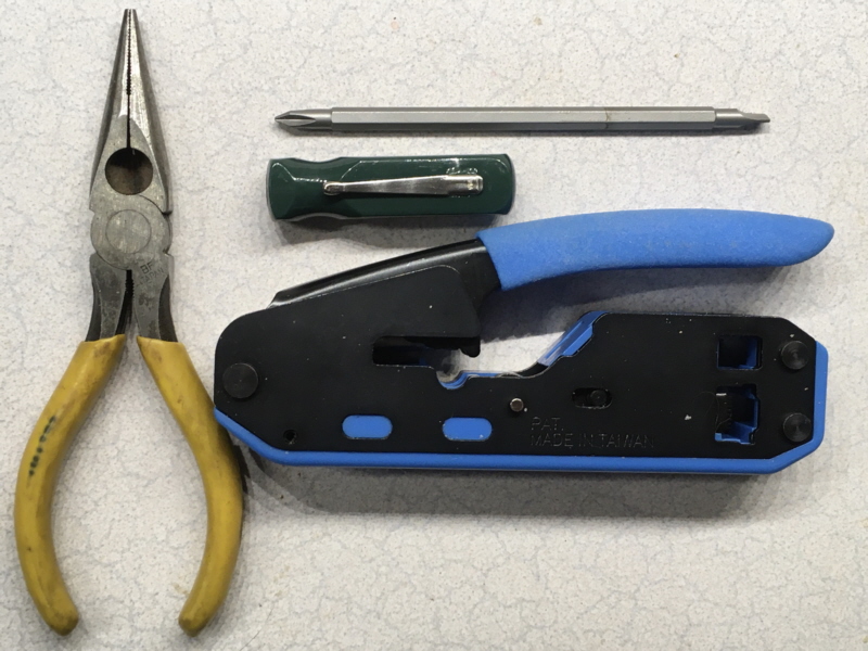


  • Diagonal Cutters (aka Dikes), Needle-nose Pliers with cutter, Electrician's Pliers with a cutter, or a Cable Cutter (for cutting video cable) in excellent (sharp) condition. Don't use scissors for cutting wire! It ruins them by nicking their cutting (shearing) edges.
  • Small #1 Phillips and flat tip screwdrivers (photo shows a reversible); almost made this optional, but it's very handy for a variety of tasks with consumer electronics.
  • Connector Crimping Tool with built-in outer sheath stripper. The one in the photo is made by Ideal and it's an excellent value for the price at about $25 from Amazon. It's nearly identical to the Klein Tools crimper and much less expensive. I like this style which has plenty of crimping leverage without the long jaws and handles. Fits in a small tool bag or tool pouch pocket, and it's smaller than the cable tester. This one can also handle RJ11/RJ14 phone plugs. However, it's made for the blind plugs, not the pass-through (see below). Klein makes a simple RJ45 (only) crimper, the VDV226-005, that's about the same size and price, and trims the wire ends off a pass-through style plug.
  • RJ45 plugs rated for Cat.5e and Cat.6 cables and data speeds. Two types of plugs. One is a blind termination with a solid plug end that requires cutting the wires to a proper length to fit to the plug end while having sufficient jacket for the crimping wedge to hold the entire cable in the plug. There's a narrow range of wire length of about 1/2" and all the wires must be very nearly the same length. Cutting the right length before insertion into the plug requires a bit of experience. The other kind in the bottle are "pass-through". With individual wires passing through the entire plug, they're easier for beginners to assemble and verify correct wire position visually. The wires can be cut at a slight angle letting the insertion get one wire placed properly at a time. The downside is having to trim off the excess wire flush to the plug end. Some crimping tools are made for these plugs and have a guillotine at the end of the plug that does this when it's crimped (e.g. the Klein mentioned above). Most diagonal wire cutters and cutters built into pliers cannot cut sufficiently flush with the end of the plug after crimping. The manual trimming method is pushing the cable hard into the plug, cutting as flush as possible manually before crimping, pulling back very slightly, and then crimping. Small diagonal cutters can get very close. Big ones don't work so well. A utility knife can also be used, very carefully to avoid trimming the end of your finger off with the wires. If too much protrudes, the plug won't seat fully into a jack. Unless you're dealing with 23 AWG cable, which is usually Cat.6 with solid copper wire for long distribution runs in overheads, plenums, and walls, the Cat.6 used for patch cables is typically 24 AWG stranded copper as the cable is subjected to being frequently flexed. I usually use 24 AWG Cat.5/Cat.6 rated plugs, but have used plugs made for 23 AWG without any problem. It's not quite as tight when the plastic wedge is crimped over the jacket though, increasing the importance of strain relief where the cable enters the plug. Plugs are dirt cheap from places like Amazon - typically 100 of them for about $5-$6 - and Amazon shipping (vs 3rd party seller) is free with Amazon Prime.
  • RJ45 strain relief anti-snag hoods. These not only provide some strain relief on the cable as it enters the plastic plug, they also protect the locking tab, to prevent it from breaking off as easily. There are a couple styles of anti-snag strain relief. I prefer these but they add to the width and height of the plug. Another type is the same width and height with tabs that fit into the back of the plug plus another flexible tab that extends over the top of the locking tab. The type is a matter of preference. IMO the ones in the photo are better for anti-snag but a tight fitting plug can be a bit harder to get out of a jack, especially on a switch or router with closely spaced jacks. Unless there aren't any on hand for an emergency cable repair, a strain relief that protects the locking tab is a must. The strain relief anti-snag hoods are just as cheap as the plugs. Total parts cost is about $0.10 - $0.12 per RJ45 plug replacement (if you do it carefully and get it right the first time; check twice; crimp once).

Optional (makes life easier but adds cost):


  • Magnifier, preferably on a table stand, or worn on the head that can be flipped up, but a hand-held works fine if that's what you have.
  • Cable sheath cutter. The crimping tool should have one but these can be more convenient. Comes free in some packages of RJ45 plugs.
  • Cable tester. These can be had from $10 to over $100. Don't buy the cheap Chinesium $10 tester. It will work once or twice and then inexplicably quit. I had a couple (past tense) and learned after the 2nd one went belly up after two or three uses. This one from Southwire was about $65 from Amazon. It's overkill for simple cable plug replacement although it's got a lot of bang for the buck compared to others. Southwire has a basic model, the M550, for about $31 on Amazon that will verify you got it right, or tell you what the fault is, and it's an excellent value. Like this one it can also test video cable. Doesn't have an RJ11/RJ14 jack but can be pressed into service with phone cables if you know what you're doing (a phone cable is typically very easy to inspect).
  • Swiss Army Knife "Super Tinker" (by Victorinox). Has a big blade, little blade, can opener, bottle opener, and most important, a #2 Phillips screwdriver, and scissors. The Phillips is much more useful for cable repair than a corkscrew. The scissors come in handy snipping a little more insulation jacket, cutting a center divider (most Cat.6 has it), and the string sometimes found inside the cable. (Not for cutting wire - that's what the wire cutters are for.) A Deluxe Tinker adds a small pair of slip-joint pliers, but small needle-nose are more useful.

Preparing the Cable . . .

  1. Cut the old RJ45 off using the cable or wire cutters and pitch the broken connector into the rubbish bin.
  2. Put the strain relief onto the cable end in the correct orientation. I've forgotten to do this and had to start over. Embarrassing. I do it right after lopping off the broken RJ45 now.
  3. Strip about 2 inches of cable jacket off of the cable, exposing the eight wires in four twisted pairs. Here I'm using the stripper built into the crimping tool.
  4. Spread the pairs apart. There will be an orange pair, a blue pair, a brown pair and a green pair I arrange them with the orange on the left, the blue away from me in the middle, the brown on the right, and the green toward me opposite the blue. Makes it easier for me to arrange the wires in order in the next part.

Untwisting the Pairs and Arranging Wires in Proper Sequence

  1. May seem counter-intuitive, but the locking tab is on the bottom of the connector. The contacts are on the top of the connector. As the end of the top is facing away from you, the pins are numbered 1-8 from left to right. The sequence of them isn't arbitrary, it's based on best crosstalk reduction and resilience to electrical interference from other nearby devices for maximum Cat.5e data throughput, which carries over into Cat.6 and Cat.7. There are two standards for the wiring sequence, T-568A and T-568B. If you look at the top (tab side down) of an Ethernet RJ45 you'll very nearly always see the T-568B color sequence. The difference between T-568A and B are the swapping of the orange and green wires. From a data throughput standpoint they have the same performance. The "A" has history in legacy USOC telephone wiring with the blue and orange being used for Line #1 and Line #2 respectively. It continues to be specified and required in some government contract work, but the rest of the world uses T-568B. It doesn't matter technically if both ends of a cable are one or the other, as long as they're both the same, but it's considered very bad practice to mix T-568A and T-568B cables in the same installation and system. Someone coming along later may very well see one and do a repair on a different cable assuming the entire installation used that standard when it didn't, ending up with a cross-wired cable. The average patch cable repair DIY'er should just use T-568B as it's likely all you will ever see in your lifetime. The last time I saw the T-568A color sequence was dealing with a PSTN telephone system decades ago, and it had nothing to do with Ethernet and digital data transmission. Everything Ethernet beyond four wire Cat.3 has all been T-568B. Unlike modular two-wire and four-wire telephone cables, both ends of a standard Ethernet cable should be wired the same. A "crossover" cable is a different animal with very special and unusual application. All current equipment will detect whether or not it should have a crossover and configure itself accordingly. Been that way for quite a few years now - to avoid the need for identifying those rare occasions requiring one. I've seen old documentation from the Cat.4 and Cat.5 era stating T-568A on one end and T-568B on the other end creates a cross-over cable. Not so in the current Cat.6 and Cat.7 era that can use all eight lines for full duplex Gigabit. Don't do it and you'll stay out of trouble. Make both ends T-568B.
  2. The wires should be untwisted and laid out from left to right as they will be inserted into the plug. This is why I had the green closest and blue farthest. It allows placing the green stripe and solid green around the blue pair. They alternate striped and solid, even though the green pair is split up around others. Get the wires as straight as possible. If using a pass-through style plug, you won't need to trim them down.
  3. In this repair I used a blind end plug and needed to trim them down after getting them in the proper sequence working them around to get them aligned with each other. I cut them with the diagonal cutters (not the scissors) while holding them firmly, and then continued to work and flex them some to get them more relaxed in the proper order.

Plug Assembly and Crimping

  1. Assembly into the plug which, should be done with the locking tab facing down can require some finagling to get the proper colored wires into the correct holes. The wires in some cables seem to have a mind of their own. There is a learning curve to doing this and it slowly gets easier with experience, especially with blind end plugs and the variants that have staggered wire holes. It's gotten much easier for me. The DIY'er who doesn't do them very often would probably find the pass-through easier to work with. For the non-staggered (vertically), I've found keeping the wires toward the top tends to guide them easier. For the plugs with vertically staggered holes (half slightly higher than the others) it can take a bit of wiggling. Don't force it, you'll just bend the wires and have to pull it apart and straighten them out.
  2. This is the time to do an inspection to ensure all the colors are in the proper holes. Use a magnifier if necessary, looking at not just the top, but the bottom as well even though it's more difficult through the tab. Take care that the plug doesn't slide off (been there, done that). Some striped wires are very sparsely striped. If one is out of order, pull it apart, reposition the wires in the proper sequence and go at it again. Patience is important and it gets quicker with experience. The pass-through is very easy to inspect and verify. Look twice; crimp once. Avoids wasting a plug and having to start all over from the beginning.
  3. Once you've verified they're all in the correct holes, the connector can be crimped using the crimping tool. A decent tool doesn't need to be expensive, but avoid the cheap $5 Chinesium crimper. They're sloppy and frustrating to work with. This Ideal is nearly identical to the Klein and was barely over $20 from Amazon. I was impressed when I unwrapped it and used it the first few times. Doesn't need that much force. You can tell when you've bottomed out from the feel of the tool. No point in cranking down with yet more force. It's not going to do anything except make your hand red.

Inspection, Strain Relief Assembly, and Test

  1. If you did the inspection right before crimping, this should be perfunctory, but it's worth a look anyway. Bad news never improves with age. If it's not wired correctly, it's not going to work when installed. May as well know it now. In addition to verifying color sequence again, I also look at the wedge that holds the cable in the connector, and contact penetration through the wires. Here, the three spear-point tips of the contact can be seen protruding from the bottom of the brown wire.
    More spear-point tips can be seen looking at the wires through the plug bottom. A magnifier can help, but even with that, looking through the locking tab at the center wires isn't very easy.

  2. Slide the strain relief over the rear of the plug and over the top of the locking tab. Shouldn't require much force. Some cables are larger in diameter than others which might require a bit of wiggling to move one that's a bit tight on the cable. You should know from feel and how far the locking tab is in or under the anti-snag hood when it's all the way on.

  3. If you have a tester, the final step is testing it. If everything was done properly, this should be a perfunctory verification, but if there was a mistake, Bad News never improves with age. Better to know now than later after installing the cable. It also verifies the insulation displacement tines on the contacts have done their job properly. This cable passed (difficult to read in the photo), with one end in the top of the tester and the other in the remote receiver. All of yours should also pass.
Go forth, be fruitful, and fix those Ethernet cables with broken locking tabs that are worth salvaging. Eventually, you may decide to give up buying finished cables and fabricate your own Ethernet patch cables cut to the length you need instead of having to live with one that's the next size longer than you need (or want), requiring you to loop it up and hide the loops somewhere. I just bought 1000 feet of 24 AWG copper stranded wire Cat.6a cable (made for patch cords), for about $133 on Amazon ($0.133 per foot), with free shipping to my doorstep (all 30+ pounds of it). Should last me for the rest of my lifetime. A 10 foot Cat.6a cable costs me about $1.50 in materials, and a 25 foot is roughly $3.75 which are very difficult prices to match for 550MHz Cat.6a rated cables.

One final tip . . .
Electrical cords should never be folded up flat and squished. It's very hard on the wires, and causes more resistance with the electrons having to go around hairpin turns (no joke, this is real). It's hardest on cables like these that have very fine wires in them, and it's a leading cause of cable failure other than the plugs. Excess cable should be coiled. I use thin strips of Velcro to hold the small coil. Likewise, stored cables should always be coiled up, without twisting them. I hate it when I unpack a new electronic device and see the thin power cable from the wall wart to the device folded up and smashed flat. Very bad practice, but seemingly commonplace. I always untie them and loop them into an untwisted coil, attempting to get rid of as much folded up memory as possible.

John

Saturday, March 24, 2018

Broken Computer Desk Door Replacement

Broken Computer Desk Door

Accidentally hit this door on the right pedestal of my computer desk. It's made out of pressed wood with a thin laminated fake wood veneer. When the door went past the hinge limit it broke the upper and lower corners with the hinge pins off. Didn't take much force; not with 1/2-inch pressed wood. I hate the stuff and wouldn't have bought a desk made of it (someone who shall not be named bought it). I'd have built my own. Nevertheless, the broken door sat leaning up against the desk for a while. Photo shows the old door with the handle hardware removed.

Got tired of looking at it after a few weeks. Time to replace it with 1/2-inch birch plywood, about the same natural color as the rest of the desk. I've got all the tools required to quickly fabricate the new door. Birch plywood is frequently used for simple cabinetry and craft projects. It's not a hardwood, but it's not a soft wood like pine or fir either. Has seven layers, not counting the two birch layers, one on each side. Its pale color is easy to stain to a desired shade. The large number of layers makes it extremely stable and quite strong, resisting warping, even under load when used in shelving, if it's the proper thickness. I've used oak and birch plywood in furniture where the edges would be concealed for that reason. A 12" x 24" piece was a couple inches larger than the ~11" x ~20"original door and it was cheap on Amazon, with free shipping. Arrived on my doorstep in two days.

Panel Cutting With 10-inch Table Saw


The first step was cutting it down to proper size. A table saw with the proper fence and fixtures is the perfect tool for making precision rectangular panels with perfect right angle corners. This was my father's 1954 Craftsman 10-inch table saw. As far back as I can remember, this saw sat in our garage. Dad used it for just about ever project involving wood and lumber, including dressers, desks and a hobby horse to ride on when I was 3 years old. Those that know vintage Craftsman shop tools will recognize the "Craftsman Gray" color. They don't make them like this any more. Has a heavy cast iron bed and the blade is belt drive. The blade arbor can be raised to within a fraction of an inch of the table top. A 10" diameter blade can cut through 4" rough cut lumber. Many saws are direct drive with the motor severely limiting how much of the blade can protrude through the top. First step is ensuring the blade is at a right angle to the table using a small square. The rip fence isn't original. Left a lot to be desired in making furniture. It was made from cast aluminum and part of it had cracked from clamping stress over the years. Replaced it about fifteen years ago with a heavy-duty precision fence.

Ripping the Long Sides Parallel


Ripping the long sides and getting them perfectly parallel is done by setting the fence for the first cut about a half-inch or so more than the width needed. The second cut on the opposite edge is done with the fence set at the exact finished width. With a fine finishing blade (has more teeth than a rough cut) you get very smooth finished edges that are exactly parallel to each other. The two grooves in the saw table on each side of the blade are called miter grooves for use with a miter fence (which I won't be using for this). The yellow device with thin fingers clamped into the left miter fence groove is a device to prevent kickback of the work piece as it's slowly fed through the saw. The edge of the work piece displaces the fingers slightly which allow it to move forward, but prevent the saw blade from pushing it backward. These work extremely well. Anyone who's witnessed a table saw kickback in which the saw teeth grab onto a work piece, hurling it back at the saw operator, can attest to never, ever wanting to have that happen. It can cause very serious injury and a narrow piece of wood can impale you. The stick with the yellow tip is a "push stick". Keeps your fingers away from the whirring blade, which can lop off fingers in the blink of an eye.

Crosscutting the Short Sides Square


After the long sides are parallel, the short sides can be cut at precise right angles to them. The aluminum table extension on the left could be used as it's able to slide and can be fitted with a miter fence for making crosscuts at any desired angle. It's locked down and won't be used in this project. Neither will the crosscut miter fence be used. It's better for narrower pieces such as 2x4 lumber and I've got a miter saw for that. When making many right angle crosscuts on panels, it's easier to use a crosscut sled that's permanently set to a right angle. I fabricated one from birch plywood nearly twenty years ago.


It has an aluminum U-channel the same width as the miter groove on the bottom. The U-channel used is a special type, the width of which can be tweaked with some adjusting screws and wedges. It's exactly the same width as the miter fence groove in the saw table. To make it, I bolted the channel to the bottom of then plywood panel and ran the piece through the saw, which gave it a perfect edge precisely at the side of the saw blade.


For the sled fence, I added a door threshold made of ash (the poor man's oak) at a precise right angle to the sled edge that had just been cut, with the end protruding slightly over the edge. Properly kiln dried ash is very hardy and stable. Ran it through the saw again to trim the sled fence off. I've used this homemade crosscut sled for countless panels over the years. Easy to make if you know how, and worth its weight in gold when cutting furniture and cabinetry panels. Due care and time taken to ensure the sled fence is exactly at a right angle to the edge is the secret to repeatedly getting precise right angle crosscuts reliably on panels every time.


As with ripping the long edge, the first cut is made trimming a bit off one edge. The second cut is the precise one for the desired length from the other edge. With the work piece on the sled up against its fence, it gives a precise right angle on the panel. The piece trimmed off goes into the bin of wood "scraps" that can be used for something in the future. That bin has saved untold dollars and trips to the lumber store for a small, quick project.


Any doubts about whether it's square? Measure the two diagonals. If it's square, they'll be exactly the same length.

Adding the Hardware


A quick trip to the drill press for the door hardware holes. Took the measurements off of the old door for the new one. What better use as a backstop for the through holes than the old door. :-) A small Forstner bit was used to countersink the door handle screw on the inside to keep its head flush with the inside surface. Instead of the original wood screws, I used pan head machine screws through the door panel on the hinge pins. This will prevent them from being pulled out if there's stress on the pins.


Back side of the old door on the left, and the finished new door on the right with all the hardware attached. The small black rectangle in the upper right corner is the steel plate for the door latch magnet to hold the door closed. There are a few extraneous holes in the old door are from using it as a backstop on the drill press when drilling the holes in the new door. :-)


Front side of the old door on the left, and the new door on the right with all the hardware attached. Project almost finished.

Installing the Door


New door installed on the computer desk pedestal. It's very nearly the same color as the desk's pressed wood laminate. Fits perfectly with an even gap all the way around. Measure twice and sometimes thrice. Cut and drill once. I may take the door out at some time in the future and add some clear semi-gloss urethane to it. It's in a very benign environment, so it doesn't need much protection from moisture or humidity.

Bonus Photo


If you thought the table saw was vintage, this was my Dad's 1936 vintage 13-inch band saw. I remember when he bought it used in the mid-1960's. For those familiar with vintage Craftsman, it's in pre-WWII "Craftsman Blue" livery. Although not used for this project, it still works quite well. The bed is thick cast iron. The wheels are heavy cast iron, and you can see where they drilled out material in the rims to balance them when it was manufactured. Once it spins up, the upper and lower wheels are like flywheels. The energy in them allows plowing through tough spots in lumber without bogging the saw down. They don't make them like this any more. The aluminum angle piece on the left is used as a fence, and the C-clamps on the right are used to clamp it to the saw's work table.

Saturday, February 23, 2008

iPod Mini Lazarus Act

Resurrecting an iPod Mini From the Dead

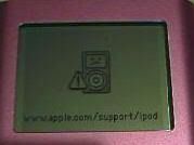
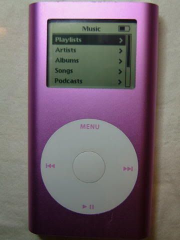
A friend at work asked me if I could resurrect an iPod Mini that booted to the dreaded "Sad iPod Icon." Told her I'd give it a shot, thinking one of the "5 R's" would bring it back to life. My wife has always managed to cure her own iPods, so I knew there was a source of advice available on what things can be tried to get it working again. Although she has a whole family of various iPod models, none of them is a Mini. Little did I know at the outset that it would be a little more work than fiddling with some button combinations on the click wheel to reset it and restore the operating software, if necessary.

I got my first clue of this when the iPod Mini was delivered to me by my friend. She told me they had already been through Apple's "5 R's" several times without avail. Not a good sign. Nevertheless, I took it home and went through them a couple times myself, including trying to put the iPod into mass storage drive mode. Same results as she had. Nothing more could be prodded out of it beyond the "Sad iPod" screen. OK, off to the computer and the search engine of search engines: Google. What I didn't know before getting pages of hits about the iPod Mini and the "Sad iPod" icon was soon revealed.

The Bad News:
With an iPod Mini, it's almost always catastrophic drive failure. This isn't just the file structure hosed up on the drive that reformatting it can fix. That would produce a file folder icon with an exclamation point.

The meaning of a "Sad iPod" icon on a Mini:
[with apologies to Monty Python]
The drive isn't just restin' from playing the LP version of Iron Butterfly's "In-A-Gadda-Da-Vida," or pinin' for The Beatles' "Norwegian Woods." Even 4 million volts wouldn't make it "voom" again. It's passed on; the drive is no more; ceased to be; expired and gone to meet its maker; a stiff. Bereft of life, it rests in peace. If it were't captive inside the iPod, it'd be pushing up the daisies. Its electro-mechanical processes are now history; off the twig. It's kicked the bucket, shuffled off its mortal coil, run down the curtain and joined the choir invisible. It's an EX-DRIVE!

The Good News:
Powering up with an Apple icon and displaying the "Sad iPod" icon almost always means the logic board (main circuit board) and display are OK. Very, very likely the click wheel and daughter board with earbud jack are OK too. More Good News: the iPod Mini can be disassembled and the original Seagate ST-1 MicroDrive replaced with a CompactFlash card.

Better News:
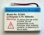
While it's cracked open for major thoracic surgery, might as well replace the battery too. Age and repeated recharging has likely reduced its capacity (translates into playing time). The original battery Apple used was rated at 400 mAh capacity. Target offers 400 mAh replacements for $40. Surprisingly high priced as on-line (easily found) sellers of iPod parts offer 650 mAh significantly higher capacity (~1.5X) drop-in replacements for 2/5ths of Target's price, including shipping cost. Better yet, CompactFlash also uses less power than a MicroDrive. An iPod Mini with both CompactFlash and new 650 mAh battery won't run just 1.5X longer between recharges, it will run even longer, likely 2X or more.

The Best News:
At the time the iPod Mini was originally designed and made, MicroDrives were expensive. That's why Apple only used 2GB and 4GB drives. CompactFlash was emerging as a drop-in direct replacement for MicroDrives using flash memory, but it was even more expensive. Hitachi and Seagate still make MicroDrives, offering models with as much as 8GB capacity, but they remain expensive. The price of CompactFlash has since plummeted while capacity and read/write speed has increased dramatically. A 133X CompactFlash with 8GB, twice the capacity of an iPod Mini 4GB MicroDrive, now costs 1/4th the price of a 4GB replacement Seagate ST-1 MicroDrive, and while the capacity of a MicroDrive now tops out at 8GB, the capacity of CompactFlash has risen to 32GB. Designed as an end-user removable memory, it's most often found in this kind of application with some PDAs and most professional grade digital SLR cameras. Devices like the iPod Mini have them embedded inside, and they weren't intended to be end-user removable. Consequently, not every make/model CompactFlash works well inside an iPod Mini. Scouring a number of reviews showed the Transcend 133X CF cards worked well with decent write speed (when uploading music into the iPod; read speed during playback is at a comparatively very slow rate).

Now to get the iPod apart and extract its MicroDrive. I just happen to have memory card readers on two desktop machines that have a slot for MicroDrive/CompactFlash memory cards.
[with apologies to Frank Baum]
Attempting to read it directly will verify it legally, to see if the MicroDrive, is morally, ethic'lly, spiritually, physically, positively, absolutely, undeniably and reliably dead.

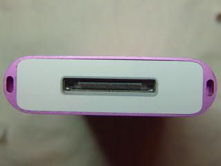
Examining the outside, the mechanical design concept for its case is obvious. It is an extruded aluminum shell with plastic top and bottom caps, with two holes in the front for the display window and click wheel switch pad. What isn't obvious is how the plastic top and bottom caps are attached. There are no fasteners (screws, nuts, rivets, etc.) visible and there are no labels or bezels that could be concealing fasteners.  That means the top and bottom plastic caps must either snap on or be held in place with an adhesive or glue. Turns out, after a little more Google work, that they're held in place on metal plates just under them with adhesive. However, they're thin and can be easily broken if removal is attempted too aggressively. Past experience has taught me that getting an adhesive to "release" requires just enough tension applied and patience to allow it to slowly give way. The bottom plastic cover is more fragile than the top too, with its wide rectangular hole for the docking connector and thin strips of plastic above and below the hole.

A small and extremely thin knife blade edge can be slipped between the aluminum shell and the plastic top and bottom caps. The trick is not going too deep and damaging any components immediately under the cap, or break the guide pegs on the underside of the caps around their edges (aids installation of them during assembly and adds a little strength when completely assembled). Some gentle sideways prying, just under the cap edge (not on anything under it) and alternately working both the front and back long edges eventually releases the adhesive. Some folks suggest using a hair dryer to heat the caps (and the adhesive) to help it release. Yes, it could help as hot adhesive usually doesn't hold as well, but controlling the amount of heat and where it's directed is difficult. Even if the hair dryer is on its "low" setting it could warp the plastic, and too much heat on the click wheel could damage it too. I avoid using any form of hot air "heat gun" if at all possible. Room temperature and patience was all that was required to get this iPod's caps off.

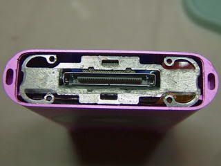
Sure enough, under the caps are metal plates. The bottom one clips into four grooves at each end of the iPod's front and back. The curved arms that clip into the grooves, and the holes in the ends of them are there to aid in installing and removing it. This photo was done during reassembly. The adhesive that holds the bottom cap to the plate can be seen clearly. I added a little more adhesive of the same type to help hold the cap on securely as the plate and cap had been handled some while they were off.

An extremely small pair of needle nose pliers, taking great care not to insert the nose tips too far into the holes allowed squeezing the clip arms and removing each side. What's found under this metal plate shows why care must be taken to not insert the blade used to pry the plastic cap off or the tool is used to unclip the metal plate under it too far into the ipod. The very thin mylar cable with copper flex traces embedded in it that connects the click wheel to the logic board is just under one end of this clip. The "button" connector on the end of the cable has a mating connector on the edge of the logic board. These types of cables are easily damaged! Go too far with a tool under the cap or plate and the cable or its connector will get damaged. A damaged the click wheel cable or connector cannot be repaired; it requires removing and replacing the entire click wheel assembly with a new one. The cable in this photo has already been disconnected from its mate on the logic board by very gently prying alternately on each side of the connector until it came loose. It's a snap fit, so it should be obvious when it finally pops out. Do not pull on the cable or exert too much force on the tab on the end if it!

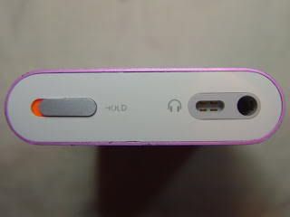
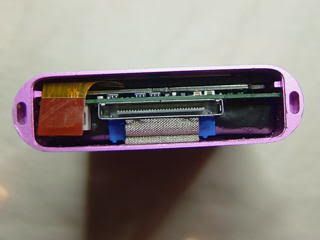
Under the top cap is another metal plate. Turns out this one is attached to a daughter board with the audio ear bud jack and "Hold" switch on it. The daughter board is, in turn, attached to the main logic board. There are two #000 size Phillips screws that attach this plate to the top end of the iPod and hold the entire logic board assembly inside the case. As with the bottom plate, the adhesive used to hold the plastic top cap on can be seen in the photo. Removal of the logic board assembly from inside the aluminum case requires removing these two screws using a jewelers driver. Ensure it's a #000 Phillips or cross-tip, one of the smallest made, as anything bigger will not fit into the heads properly and strip out the slots. The screws have non-permanent thread locking adhesive on them and they're driven in firmly when the iPod is assembled in Apple's factory. This requires firm pressure on the screwdriver pushing it into the screw head while carefully turning it. The driver can start to back out of the screw head (in spite of some pressure on it) which necessitates stopping as soon as it does so, reseating it, and trying to turn it again. The thread locking adhesive will eventually "give" and the screws will come out, but it's very important not to damage the screw heads while removing them! They are all that hold the entire electronics assembly inside the case. It also helps to work over a towel or old T-Shirt, well away from the table or bench edges, to keep from losing them when they come out. I suppose replacement screws can be had, but have never seen anything suitable as tiny as these are. They can't be replaced by a simple trip to the local hardware store! I also use a very small Tupperware container with seal (aka lid) to keep parts like this in, so they don't get lost.

Felis Catus Interruptus:
Do you ever get that feeling someone might be watching? Ever try to do fine, detailed work requiring a steady hand with someone supervising it by watching closely over your shoulder? Just as I was about to remove the two #000 Phillips screws from the top plate, I sensed being closely watched. Suddenly I was being closely supervised, by our cat, Frisky, who jumped up on my shoulder and perched there, watching everything going on. She does when she wants attention, sometimes several times in a singe evening. What she really wants is a free ride around the house perched on my shoulders, trilling in my ear and rubbing her head against mine the entire time. At least she did it before I had the Phillips driver firmly engaged in the screw head. Picture was done with my cell phone held out at arm's length. After I deposited my "supervisor" onto a high perch (she climbs from my shoulder onto it), I got back to work on the iPod.

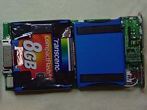
Once the screws are out, and after double-checking to ensure the click wheel cable is disconnected, the entire logic board assembly can be carefully slid out through the top by firmly pushing on the bottom docking connector. Do not pull on the top plate as this can break the daughter board off of the main logic board, and slide it out slowly. My fingers aren't that huge, but they still didn't fit far enough into the bottom of the case to push the board all the way out. My little finger was almost narrow enough. Used the eraser end of a common wooden pencil to push it the rest of the way out. The cap end of a narrow plastic pen can also be used. Push on the docking connector, not on the board or click wheel connector. The photo shows all the parts: top and bottom plastic caps, the metal plate from the bottom, and the Phillips screws from the top. All the parts except the logic board went into the Tupperware bin, sealed up and set aside until they were needed for reassembling it. Flipping the logic board over shows the drive and battery. This photo was done with the new CompactFlash drive installed, but the old battery still in place. The battery is opposite the display at the top and the drive opposite the click wheel at the bottom. The dull silver rectangle in a metal frame is actually a piece of stiff foam inside a fine wire mesh tube. It grounds the body of the drive to the logic board's ground plane and aluminum iPod case. The drive is given shock protection by wrapping its edges in a neoprene U-channel held in place with tape, along with the header connector for the drive that has a very short ribbon cable running to a tiny board connector (hidden by the battery). The small piece of copper conductive tape also wraps around the blue neoprene channel to provide a conductive path from the metal plate on the drive to the grounded wire mesh. The battery is attached with a very small square foam adhesive pad to the top of a small integrated circuit chip on the board.

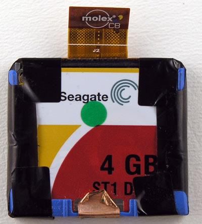
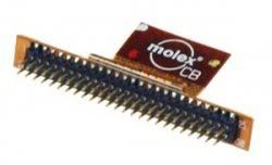
The battery must be at least pulled up and away from the board as most of the drive interconnect cable and its connection to the logic board are under the battery. The battery is held in place, primarily to keep it from shifting around inside the iPod with a very small square of thin adhesive foam pad. After the drive has been disconnected from the logic board, the tape, shock absorbing frame and interconnecting ribbon cable must be removed. The short interconnect cable was made by Molex, a major name brand of industrial, commercial and military electrical and electronics connectors. The double row of header pins mate with a matching double row of header holes on the top edge of the drive. The double row of pins can be seen inside the MicroDrive/CompactFlash slot of a memory card reader. Once I had everything removed from the MicroDrive, it could be tested in the MD/CF slot of the memory card reader in my desktop computer.

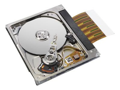
Slid the drive into the MD/CF slot in the memory card reader, and the card reader's LED lit up (meaning a memory card has been inserted into one of its four slots). Not loud enough to be heard while inside the iPod, a soft grinding sound lasting about two or three seconds was emitted by the MicroDrive after it was inserted into the memory card reader. This kept repeating continuously until I pulled the drive out of the card reader. The computer's O/S also did not acknowledge the presence of a removable drive. Even if it were completely unformatted, the O/S (Windows XP) should at least come up with a dialog box offering to format the drive. I have more than one desktop machine, and all of them have memory card readers. So, it was inserted into the MD/CF slot in a second destop computer which resulted in exactly the same behavior as when it was in the first one. The picture shows what the inside of a Seagate ST1 looks like. Most likely the repeating grinding sound was the read head arm trying to deploy or move to read the drive platter.

[more apologies to Frank Baum]
I must aver, I thoroughly examined her. And she's not only merely dead, she's really most sincerely dead.

With the new drive and battery installed, reassembly is simply the reverse of disassembly. I added some thin adhesive strips to the top and bottom plates to rejuvinate what was there as handling them, along with the plastic end caps had likely degraded the original adhesive some. It's a very similar, non-permanent adhesive, which means the caps can still be removed at some point in the future if necessary.

After the iPod was completely reassembled, it was time for the infamous "Smoke Test." Contrary to popular belief, promoted by electrical engineers world-wide, electronics do not run on electricity or electrons. It's one of the greatest hoaxes ever foisted upon mankind. They run on pressurized smoke. Ever see an electron? I daresay everyone has seen smoke though. The proof of this is seeing the smoke leak out when electronic devices fail. Disengaged the "Hold" switch on top and depressed the center click wheel button. The iPod sprang to life with the Apple logo followed by a file folder with exclamation point icon. It's what I had expected as the CompactFlash drive had been formatted, but didn't have the iPod software installed yet. Much, much, much better than the Sad iPod icon. Best of all, no smoke leaked out. Connected it to the USB port on my computer, reinstalled the iPod software, including updating to the most current version and was rewarded with a full iPod Mini menu. Loaded some music, started the iPod playing, and exercised all the click wheel functions. Works just like a new iPod Mini! It's now headed back to its owner, who I hope will be tickled pink that her iPod has been resurrected from the dead, with twice its original drive capacity, and just a hair over 1.5x its original battery capacity. The iPod seems to be with its new lease on life.

Suggestion for this iPod's new name: Lazarus!

Welcome to JLind.net

Dedicated to the Practice of Polymathy Polymathy: The possession of learning in many fields. Your host is John Lind. Here you wi...