Much Cheaper Than a New One:
Custom Desktop Computer Rebuild
 It had been a while since I had upgraded my main desktop machine. Been building my own custom desktops since the mid-1980's, starting with a PC-XT clone with an Intel 8088 processor, 640kB RAM (yes, kB) 30MB (yes, MB) hard drive, Hercules graphics, and a 14" monochrome monitor. The technology has changed substantially since that first machine, and my primary desktop has evolved through an Intel 286, AMD 386, Cyrix 486, AMD K6-2, AMD Duron (Applebred), AMD Athlon XP, and into the AMD Athlon 64 processors. Before this rebuild, my main desktop was running an AMD Athlon 64 Socket 939 4000+ and AGP 8x graphics. It's upper the limit of Socket 939 AMD processors, with AGP or PCIe graphics. By no means a slouch in speed (faster than most current mid-level machines), it was time to upgrade it to multi-core processor and PCIe graphics.
Had some decision-making to do. There is some system design required when doing a custom build. One can't push any hardware combination together and expect it to work well. It might, but it might not. Learned that the hard way when I started building my 386 and 486 machines. Nearly all compatibility considerations are driven by the motherboard and its chipset. However, it shouldn't be the first choice. I choose the processor and desired chipset (Northbridge / Southbridge). Then I look for a motherboard with the chipset that supports the processor.
Looked at both AMD and Intel processors. Intel holds the edge on speed, but that's at the bleeding edge of processor technology, and they're quite expensive. Back down slightly to the top end of AMD's processors, and they're less expensive than the equivalent Intel. In the process, I discovered the AMD quad-core processor clock speeds were still substantially lower than top end of AMD's dual-core. In addition, current operating systems and application software are still geared for the lowest common denominator in the majority of machines in the current "installed user base": 32-bit single-core processors. Even the default install for Microsoft's newest operating systems, Vista, is 32-bit. The latest budget machines are still shipping with 32-bit processors (check out what's inside many of the "loss leaders" in the computer store ads). I opted once again for another AMD processor, a Socket AM2 Athlon 64 X2 6400+ dual-core with 3.2 GHz core clock. One of the chipset makers I've used heavily in the past, Via Systems, basically stopped supporting AMD processors with the Socket 939 and 940 Northbridge/Southbridge chipsets. Disappointing as nearly all their chipsets were excellent. The only real choices for an AMD Socket AM2 or AM2+ are the AMD and nVidia chipsets.
Which one picks also tends to lock in which graphics chipset will be used: ATi (owned by AMD now) or nVidia. It is possible to use an nVidia graphics card on an AMD chipset motherboard, and vice versa, as the PCIe socket it is plugged into, and the graphics interface behind it is an industry standard. However, it doesn't allow leveraging on enhancements that can be had if an ATi graphics card is used with an AMD chipset motherboard, or an nVidia card is used with an nVidia chipset. This is especially true if one wants to run multiple graphics cards in tandem (i.e. ATi CrossFire or nVidia SLI). I've used nVidia graphics for a long time (4000, 5000, 6000 and 7000 series) and have always been pleased. After looking at the nVidia and AMD Northbridge/Southbridge chipsets though, I settled on the AMD's 790FX and SB600 chipset. These are found on AM2+ motherboards which support dual, triple and quad-core processors. If I wanted to upgrade to a quad later (as they gain core clock speed), I could. It meant I'd be using ATi (Radeon) graphics. After reading some about ATi's Crossfire, I picked ATi's HD3870 with plans to use a pair of them in CrossFireX mode. The current bleeding edge is the HD4870, but they're expensive. Could have gone with HD4850, one notch down from the 4870's. It was pretty much a coin-toss until I found substantial rebates on a pair of HD3870's. Added up the power requirements for all this and realized quickly I'd need a new power supply; one that's bigger than the solid 500 Watt that's been used for several generations of motherboards. It wouldn't be enough for the processor and pair of graphics cards.
The new hardware architecture was settled:
It had been a while since I had upgraded my main desktop machine. Been building my own custom desktops since the mid-1980's, starting with a PC-XT clone with an Intel 8088 processor, 640kB RAM (yes, kB) 30MB (yes, MB) hard drive, Hercules graphics, and a 14" monochrome monitor. The technology has changed substantially since that first machine, and my primary desktop has evolved through an Intel 286, AMD 386, Cyrix 486, AMD K6-2, AMD Duron (Applebred), AMD Athlon XP, and into the AMD Athlon 64 processors. Before this rebuild, my main desktop was running an AMD Athlon 64 Socket 939 4000+ and AGP 8x graphics. It's upper the limit of Socket 939 AMD processors, with AGP or PCIe graphics. By no means a slouch in speed (faster than most current mid-level machines), it was time to upgrade it to multi-core processor and PCIe graphics.
Had some decision-making to do. There is some system design required when doing a custom build. One can't push any hardware combination together and expect it to work well. It might, but it might not. Learned that the hard way when I started building my 386 and 486 machines. Nearly all compatibility considerations are driven by the motherboard and its chipset. However, it shouldn't be the first choice. I choose the processor and desired chipset (Northbridge / Southbridge). Then I look for a motherboard with the chipset that supports the processor.
Looked at both AMD and Intel processors. Intel holds the edge on speed, but that's at the bleeding edge of processor technology, and they're quite expensive. Back down slightly to the top end of AMD's processors, and they're less expensive than the equivalent Intel. In the process, I discovered the AMD quad-core processor clock speeds were still substantially lower than top end of AMD's dual-core. In addition, current operating systems and application software are still geared for the lowest common denominator in the majority of machines in the current "installed user base": 32-bit single-core processors. Even the default install for Microsoft's newest operating systems, Vista, is 32-bit. The latest budget machines are still shipping with 32-bit processors (check out what's inside many of the "loss leaders" in the computer store ads). I opted once again for another AMD processor, a Socket AM2 Athlon 64 X2 6400+ dual-core with 3.2 GHz core clock. One of the chipset makers I've used heavily in the past, Via Systems, basically stopped supporting AMD processors with the Socket 939 and 940 Northbridge/Southbridge chipsets. Disappointing as nearly all their chipsets were excellent. The only real choices for an AMD Socket AM2 or AM2+ are the AMD and nVidia chipsets.
Which one picks also tends to lock in which graphics chipset will be used: ATi (owned by AMD now) or nVidia. It is possible to use an nVidia graphics card on an AMD chipset motherboard, and vice versa, as the PCIe socket it is plugged into, and the graphics interface behind it is an industry standard. However, it doesn't allow leveraging on enhancements that can be had if an ATi graphics card is used with an AMD chipset motherboard, or an nVidia card is used with an nVidia chipset. This is especially true if one wants to run multiple graphics cards in tandem (i.e. ATi CrossFire or nVidia SLI). I've used nVidia graphics for a long time (4000, 5000, 6000 and 7000 series) and have always been pleased. After looking at the nVidia and AMD Northbridge/Southbridge chipsets though, I settled on the AMD's 790FX and SB600 chipset. These are found on AM2+ motherboards which support dual, triple and quad-core processors. If I wanted to upgrade to a quad later (as they gain core clock speed), I could. It meant I'd be using ATi (Radeon) graphics. After reading some about ATi's Crossfire, I picked ATi's HD3870 with plans to use a pair of them in CrossFireX mode. The current bleeding edge is the HD4870, but they're expensive. Could have gone with HD4850, one notch down from the 4870's. It was pretty much a coin-toss until I found substantial rebates on a pair of HD3870's. Added up the power requirements for all this and realized quickly I'd need a new power supply; one that's bigger than the solid 500 Watt that's been used for several generations of motherboards. It wouldn't be enough for the processor and pair of graphics cards.
The new hardware architecture was settled:
- AMD Athlon 64 X2 6400+ Dual Core
- AMD 790FX Northbridge and SB600 Southbridge
- AM2+ socket motherboard with ATX form factor to fit case
- 4 GB DDR2 800 MHz (PC6400) low latency RAM (4-4-4-15-T1 timing)
- Two ATi HD3870 Radeon cards in CrossFireX
- Sony DRU-865S SATA DVD/CD Burner (with Lightscribe)
- 850 Watt Antec power supply
- 300 GB SATA II hard drive (reused from current machine)
- 3.5" micro-floppy drive (reused from current machine)
- Flash card reader (reused from current machine)
- Soundblaster Audigy SE audio (reused from current machine)
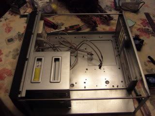 The only things to be reused in this project are the computer case, hard drive, floppy drive, flash card reader, and sound card. The case was originally bought to house an AMD K6-2 (Socket 7) system on an ATX form factor motherboard running Windows 95. It's solidly built out of heavy gauge steel; not a cheapie and worth reusing. Buying a new one with its materials and build quality, even without a power supply, would cost well over $100. The next step, after backing up the hard drive completely, was gutting it completely, down to just the case itself.
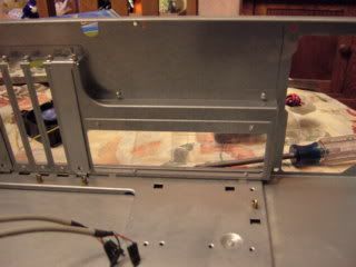 Only one problem with reusing this case though. It's a horizontal desktop box which will be a little crowded after all the new hardware is installed, and it wasn't made to dissipate the heat generated by current higher-end processors, motherboards and graphics. Although there's an air intake fan on the front, the only exhaust is out through the power supply in the back. That sufficed until now, but it's insufficient for this upgrade. Pushing the very hot air generated by current high-end processors and graphics card(s) through a power supply would be hard on it. It needs some exhaust fans on the back, and the flat panel on the back, just above the rectangular hole for the ATX motherboard connectors, is the only viable location for mounting cooling fans in the rear of the case. It's the only unused area on the case back.
Some measurements of the panel shows a pair of 60mm fans can be mounted next to each other. The task now is drilling the holes for the fans, and that requires a bi-metal hole saw. Turns out I've got one just the right size. The same size hole saw used for drilling holes in metal doors for door handles will make a hole just the right size for 60mm cooling fans. The fan mounting hole centers are marked first, and lines drawn between opposing centers locate the center point for the hole saw's pilot drill.
Only one problem with reusing this case though. It's a horizontal desktop box which will be a little crowded after all the new hardware is installed, and it wasn't made to dissipate the heat generated by current higher-end processors, motherboards and graphics. Although there's an air intake fan on the front, the only exhaust is out through the power supply in the back. That sufficed until now, but it's insufficient for this upgrade. Pushing the very hot air generated by current high-end processors and graphics card(s) through a power supply would be hard on it. It needs some exhaust fans on the back, and the flat panel on the back, just above the rectangular hole for the ATX motherboard connectors, is the only viable location for mounting cooling fans in the rear of the case. It's the only unused area on the case back.
Some measurements of the panel shows a pair of 60mm fans can be mounted next to each other. The task now is drilling the holes for the fans, and that requires a bi-metal hole saw. Turns out I've got one just the right size. The same size hole saw used for drilling holes in metal doors for door handles will make a hole just the right size for 60mm cooling fans. The fan mounting hole centers are marked first, and lines drawn between opposing centers locate the center point for the hole saw's pilot drill.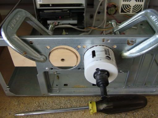 Drilling sheet metal, even if it's steel, can deform it, especially when the drill begins to break through to the other side. A piece of scrap wood is clamped to the area of the case being drilled out to provide support. The other technique is not putting too much pressure on the drill, or too high a drill speed, using just enough to let the drill's cutting edges do the work. When it does break through, there's not as much metal left for the cutting edges to grab onto and twist. It also reduces the amount of burr left behind that must be removed after drilling the hole.
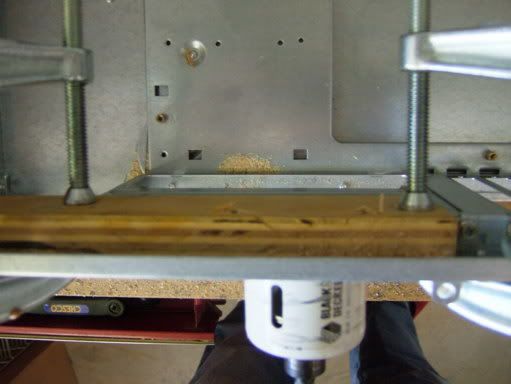 The holes have been finished and the burrs removed. The remnants of marks made to locate hole centers can still be seen, but removing those doesn't matter much. It's on the back of the case that won't be seen when the computer is in use. I used a fine-tip Sharpie "permanent" marker. Some alcohol or similar solvent would easily remove the marks if desired.
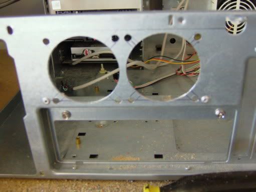 The fans have been mounted taking care to route their power cables so they don't get pinched, and won't interfere with the rest of the computer's components when they're installed in the case. The pair of fans selected are variable RPM to minimize fan noise to the level necessary for cooling. They have heat sensors on them, starting at a low RPM at room temperature, that increases fan RPM as heat from the air passing through them increases. These types of fans do the job for exhuast air; not recommended for intake fans (the air would always be cool).
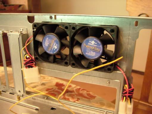 A look from the back with the new fans. I had considered adding a couple of grilles over the fans to keep things (like fingers) from coming into contact with spinning fan blades. The motor mounting in the fan box provides sufficient protection for the fan blades on these particular fans. They'll be OK without grilles over them. Note the horizontal line marked above the fans, and the small hole just above the fan on the right. The top case cover has a flange on the back, and the hole is for one of the five screws that attaches the case cover to the case. The fans had to be mounted below this line and hole as the case cover screw protrudes into the case when its cover is installed, and the fan mounting screws would interfere with the cover flange if it extended over the top of them. The fan mounting screws are nearly flush, but not quite.
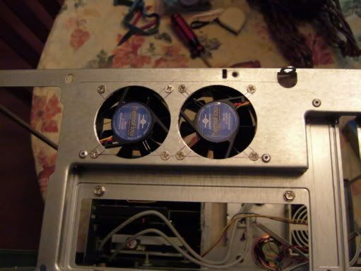 A vacuum cleaner and its hose attachment were used to completely clean all the sawdust, and more important, the metal filings out of the case. I removed and put back the drives in the drive cage while doing this. In retrospect I should have removed the CD/DVD burner, hard drive and 3.5" micro-floppy drive before drilling the holes and mounting the fans. I still use a 3.5" floppy disks occasionally. Booting from a floppy is required to flash a BIOS update on nearly every motherboard made.
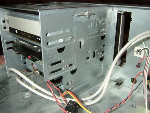 Now to deal with the motherboard. After looking at various AM2+ boards with 790FX/SB600 chipsets, reading some reviews on them, and comparing prices, I picked an MSI K9A2 Platinum that includes USB, Firewire and 1000BASE-T Ethernet on the motherboard. Even though it can handle up to four graphics cards in CrossFireX, I only plan to use two.
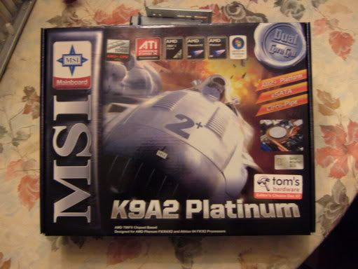 Most motherboards come with plenty of cables for connecting peripheral devices (e.g. disk drives). This one is no exception. Also included is a backplate for installation in the computer case to provide the proper cutouts for all the rear connectors on the motherboard. The original ATX form factor had a fairly standard layout for its connectors, but that didn't last long. Centronics parallel and RS-232C serial ports were supplanted by USB, Firewire, Ethernet, and embedded audio connectors. Now, eSATA ports are becomming common (this motherboard has a pair of them).
 The next step is putting the backplate into the case. All the ones I've encountered with motherboards snap into the rectangular hole for them. Occasionally the motherboard makers will use one plate for several different motherboards and some tabs on them must be tweaked or completely removed for ports and connectors on the motherboard that wouldn't need to be for a different model number motherboard. The next photo shows the backplate installed into the large rectangular hole in the back of the case. The bottom halves of the two cooling fans can be seen just above it.
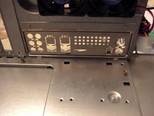 Before handling the processor, motherboard, or any of the peripheral cards, there's an essential device called an ESD wrist strap that needs to be put on and the cord attached to a ground point on the case (can be clipped to any convenient, unpainted, exposed metal inside or around the case. While many folks get away without using one, the bare processor is an extremely ESD sensitive device. It can be easily damaged by ESD. An ounce of prevention is worth a pound of cure (and the cost of a new processor).
 When doing a rebuild that includes a new motherboard, I've found it easier to install the processor into its socket on the motherboard before installing the motherboard into the case. Doing it after the motherboard is in the case necessitates reaching down inside the case which isn't impossible, but is more difficult, especially with lining up the pins on the processor with the holes in the ZIF socket on the motherboard. This processor is the "retail" version that includes a heatsink and cooling fan for it. The amount of heat generated by this 135 Watt processor can be seen from the size of the and cooling fan and the heatsink it's mounted to, complete with copper pipes to facilitate heat transfer. It dwarfs the processor IC and is one of the reasons I added additional exhaust fans to the case.
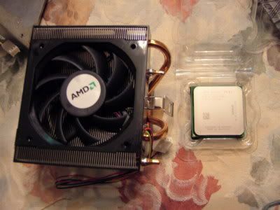 ZIF is an acronym for "Zero Insertion Force." ZIF sockets unlock to allow inserting an IC, cable, or connector with near zero "force" or friction, and then lock again after the device is seated. Processor ZIF sockets on motherboards have a locking arm along the side of the socket that's lifted to unlock it. The square socket takes a "Pin Grid Array." This processor has a grid of 940 small pins on its underside. (The four long "card edge" sockets to the left of the square processor socket are for RAM.)
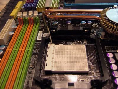 After the processor is carefully dropped into its socket, it literally drops into place when the pins are lined up correctly, the socket is locked using the locking arm and contacts inside the socket grip each pin tightly. The large black frame around the processor socket is for the heatsink, which attaches to and uses the frame to press the surface of the heatsink firmly onto the top of the processor.
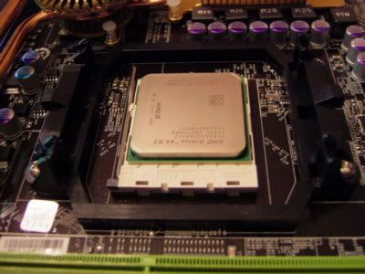 Next, the case is prepared for the motherboard. ATX form factor mounting holes are fairly standard. There are two or three variations, and some motherboards do not use all nine mounting points. Consequently, cases use removable brass studs and have threaded holes at all the possible mounting points for them. With this motherboard, I needed to move a couple of them as its mounting points were a different variant than the old motherboard. The studs are hexagonal which allows using a hex nut driver to remove and install them easily. Care must be taken to avoid over-torquing them as it can strip their threads, or worse yet, snap the stud off of its threaded end (requires extracting it from the hole to replace it with a new one; not easy to do).
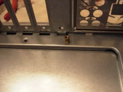 One of the cool tools I found some years ago is this one. Mounting points on the motherboard are surrounded closely by components and connectors, some of which are tall. This tool can grip a Phillips screw by the slots in its head, and it allows getting the screw started into its hole. If, perchance, the screw is dropped, it typically falls down into someplace that's hard to reach (one of many corollaries to Murphy's Law). There's a small magnet on the other end of this tool that allows retrieving it much easier than trying to use needle-nose pliers.
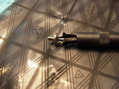 The motherboard can now be installed into the computer case. As a double-check, I count the number of mounting holes in the motherboard, and the number of brass studs in the case, to ensure they match. There's not much extra room; typical of horizontal desktop cases. Care must be taken to get all the motherboard's external connectors through the holes of the backplate correctly before installing any of the mounting screws. The bottom of the motherboard should not be dragged across the tops of the studs in the case while inserting it, but should be lifted off of them slightly when adjusting it. That can damage copper traces on the underside of the board. The screws are started using the tool above, and then tightened down firmly (again, taking care not to over-torque) using a standard #2 Phillips driver. More clues to the heat that will be generated by the motherboard are the three heatsinks on the 790FX Northbridge, SB600 Southbridge, and a third IC, all connected together with copper tubing.
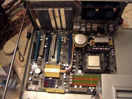 The power supply comes next. When power requirements hit exceed 650 Watts and higher, the power supplies get bigger. Because of standard mounting points and dimensions inside cases, they get longer, extending deeper into the case. This 850 Watt Antec is no exception, extending a couple inches farther toward the front of the case than the 500 Watt supply it replaced. Fortunately there's enough room between it and the drives mounted in the drive cage for the power supply and drive cables, but it's just barely enough room. The blank space just to the right of the motherboard in the photo above is now completely filled by the power supply.
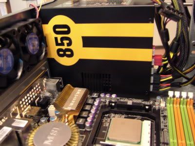 The processer heatsink/fan assembly and the RAM are now installed. Even though there are four card edge slots for the RAM, I used two 2GB "sticks" for a total of 4GB RAM. They go into the slots nearest the processor, and the heatsink crowds them a little. The fans AMD uses on the heatsinks included with a "retail boxed" processor are exceptionally reliable and quiet. The large fan size helps reduce noise as it can turn at lower RPM to move the same amount of air. The lifespan of every AMD fan I've had has exceeded every aftermarket processor cooling fan I've bought. Don't know what their service life is yet as they're all still running. It's a major reason I try to buy "retail box" versions of AMD's processors. In this case, it was less expensive than buying a "bulk pack" version of the processor (intended for manufacturers and system builders) and separate AMD heatsink/fan assembly rated for this processor (they can be found separately, but it requires some searching on-line for them). The RAM also has heatsinks; typical of low latency, high speed RAM as it must be run at a slightly higher voltage to work correctly. This generates more heat which must be dissipated. Could have used four 1GB "sticks" or one 4GB "stick" but there are reasons for using exactly two of the slots and putting identical RAM in them. An even number (versus 1 or 3) of the same size allows the motherboard to use "dual channel" RAM access which it cannot do with an odd number. This greatly speeds RAM reads and writes. In addition, if all four slots were populated, a couple RAM timing parameters would have to be slowed down slightly (at the least, the T1 in its timing specs would have to back off to T2). Using exactly two, with exactly the same RAM in each of them, allows optimal RAM access speed, to the timing limits specified for the RAM by its manufacturer.
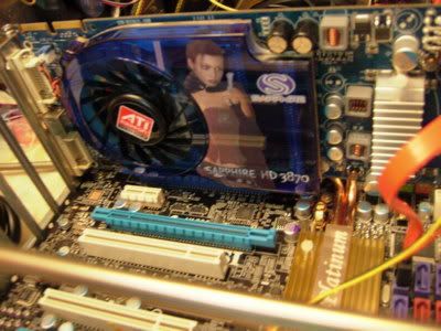
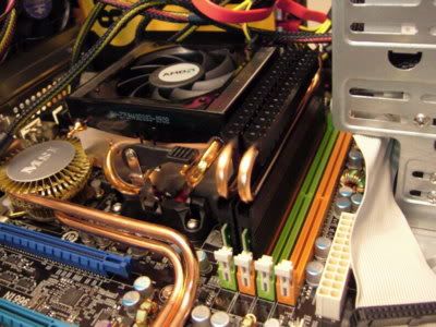 The first of the two graphics cards is inserted into its PCIe slot before adding the other cards as it's the innermost slot. The second one and CrossFireX cables will be added after the machine is up and running with the operating system, hardware drivers, firewall (I disable Windows' firewall and use one of my own), and Anti-Virus software. The size of its cooling fan and heatsinks are yet more clues about the amount of heat this system will generate.
 The remaining cards, a Soundblaster Audigy and a WiFi card, are installed in two PCI slots, and then all the internal interconnecting cables are run. Unless there's a piece of hardware that will prevent connecting a cable after all the hardware is installed, I save running all the internal cables until the end of the hardware build. Doing this keeps them from getting in the way of installing hardware, and it allows routing the cabling properly over and around the hardware as required. Doing it before this often requires re-routing cables again after additional hardware is added.
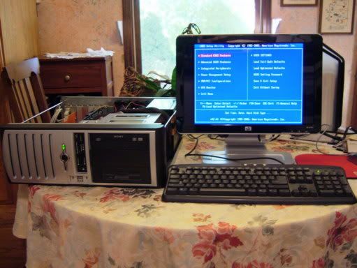
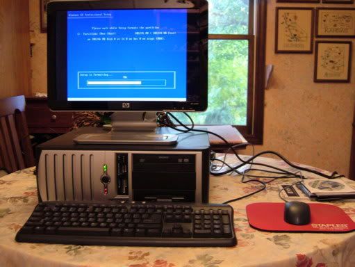
 After double checking that all the internal interconnect cables are properly installed and connected by systematically inspecting each component, it's time for the "Smoke Test" (apply power and see if anything starts emitting smoke; no smoke means at least there aren't anycatastrophic mistakes). It's the reason the CPU cover hasn't been installed yet. Keyboard, mouse, monitor and speakers (in this build, the monitor has built-in speakers) are connected, and then the power cords. Wiping the hard drive completely clean before gutting the old system prevents the machine from attempting to boot the old install of the operating system and makes accessing the motherboard's system BIOS easier. It's passed the "Smoke Test" and no errors were indicated when the BIOS performed its POST (Power-On Self-Test). The BIOS is accessed by depressing a specific key on the keyboard when the machine is powered on. The manual for the motherboard contains instructions on which key to use (typically the F1, F10 or DELETE key, it varies by motherboard manufacturer). Time to make some BIOS settings specific to the hardware in this build:
- Enabling the USB and Firewire ports
- Disabling the Serial and Parallel ports (I'll never use them)
- Disabling the on-board audio (I've installed my own Soundblaster card)
- Enabling the SATA drive interfaces and disabling the IDE drive interfaces (I'm using a SATA hard drive and CD/DVD burner)
- Disabling RAID (multiple hard drives can be configured to appear as a single one)
- Setting RAM operating voltage and timing to its manufacturer's specs
- Some additional timing parameters for the system bus (if you don't know what they are and what they do, and it isn't explained in the motherboard manual, leave these alone until you can look them up using Google).
 The cover is now put onto the CPU and the operating system is installed. The machine should not be connected to any network while installing the operating system! Firewall (if the one bundled with WinXP isn't used) and Anti-Virus software should be installed before connecting the machine to a network. The operating system is vulnerable to attack while it's being installed, and if it's allowed broadband internet access in the process, the operating system will be compromised. There are thousands of automated "bots" that scan the internet for vulnerable computers. A WinXP machine was compromised in less the 4 minutes in a test done by PC Magazine several years ago. A close friend forgot to disconnect his computer from the internet before installing WinXP. When he got done, he had to reformat the drive and start completely over. It had become a "Zombie" drafted into a Botnet Army.
I'm putting Windows XP /x64 Professional on this platform. The "/x64" variant of Windows XP is the 64-bit version of WinXP. The common variants of WinXP (Home, Pro and Media Center) are all 32-bit. They'll run on a 64-bit hardware platform, but I prefer /x64 as it was created from 32-bit Windows Server 2003 (the server version of WinXP), which came several years after WinXP Home and Pro were released. Windows Server 2003, and WinXP /x64 are noticeably more stable than the 32-bit (aka /x86) WinXP Home or Pro. It does require having true 64-bit hardware drivers for all the hardware inside the machine, and for anything connected to it using a USB, Firewire, serial or parallel ports (e.g. printers, scanners, PDAs, cell phones, MP3 players, etc.). It's not a problem now, although it was one just after /x64 was released. Even iTunes can be installed for iPods (requires an easy to perform, minor hack to iTunes for Vista /x64).
The cover is now put onto the CPU and the operating system is installed. The machine should not be connected to any network while installing the operating system! Firewall (if the one bundled with WinXP isn't used) and Anti-Virus software should be installed before connecting the machine to a network. The operating system is vulnerable to attack while it's being installed, and if it's allowed broadband internet access in the process, the operating system will be compromised. There are thousands of automated "bots" that scan the internet for vulnerable computers. A WinXP machine was compromised in less the 4 minutes in a test done by PC Magazine several years ago. A close friend forgot to disconnect his computer from the internet before installing WinXP. When he got done, he had to reformat the drive and start completely over. It had become a "Zombie" drafted into a Botnet Army.
I'm putting Windows XP /x64 Professional on this platform. The "/x64" variant of Windows XP is the 64-bit version of WinXP. The common variants of WinXP (Home, Pro and Media Center) are all 32-bit. They'll run on a 64-bit hardware platform, but I prefer /x64 as it was created from 32-bit Windows Server 2003 (the server version of WinXP), which came several years after WinXP Home and Pro were released. Windows Server 2003, and WinXP /x64 are noticeably more stable than the 32-bit (aka /x86) WinXP Home or Pro. It does require having true 64-bit hardware drivers for all the hardware inside the machine, and for anything connected to it using a USB, Firewire, serial or parallel ports (e.g. printers, scanners, PDAs, cell phones, MP3 players, etc.). It's not a problem now, although it was one just after /x64 was released. Even iTunes can be installed for iPods (requires an easy to perform, minor hack to iTunes for Vista /x64).
 After intalling the operating system, hardware drivers are installed as needed for the processor, its supporting chipset, and other peripherals (e.g. graphics and audio). The general sequence I use:
- Operating system (WinXP /x64 for this build)
- Hardware drivers
- Firewall and Anti-Virus software
- Connect machine to internet and update A-V software
- Update operating system with all critical updates (Windows Update for this build)
- Customize the Windows user interface
- Benchmark software (after which I run some benchmarks)
- Application software (e.g. MS Office, OpenOffice, Adobe Reader, Nero, various games)
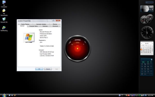
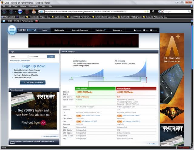 Before installing other applications, I customized the Windows XP user interface on this machine. It looks a like Vista, including a Sidebar with Widgets, but it's not Vista, it's WinXP /x64. Who needs Vista? I don't, and I don't want it either. WinXP /x64 is smaller, more efficient and very stable. It doesn't have the continuing problematic stability issues Vista still has.